MAX2606 EUT
Getting started
I love the agony of trying to get something to work. RF circuits always seem to be a particular pain point which serve to just frustrate. The MAX2606 EUT is quite the IC example on Aliexpress . It promises to be a relatively small FM transmitter with minimal components and works off a 3.3V supply. Perfect for my needs.
Now there seems to be a few people that have had success with this and many that have not. Let's try and duplicate both.
Firstly, warning! This device is small its a SOT23-6 and wiring to this requires a real steady hand and some experience. Plus, as we are dealing with RF, we need to keep leads and wires short.
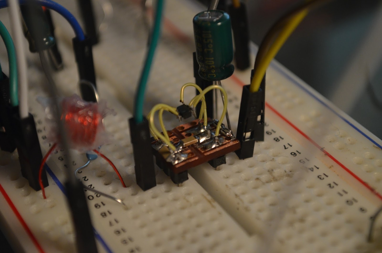
Wiring the device

This gives you an idea of the challenge ahead. It took the best part of 30 minutes to solder. Take your time. I have used an inverted strip board and cut out the tracks between. I have soldered in 2 x 3pin 0.1 inch headers and to those solder points I have used vero wire to hook up as it has the rigidity and copper area required. Its pretty stable once all soldered. The device is now like a 6 pin DIP package.
https://ca.mouser.com/Wire-Cable/Hook-up-Wire/_/N-5ggs?P=1yzoqi6Z1yx5jly
Pin #1?
As you no doubt are flooding the device with flux to get the wires soldered; you will notice the markings disappear off the top of the device. If you have trouble seeing, you may have to clean , but put in front of a bright light and you will be able to see the minor indentation of the letters.
Device data is here : https://www.maximintegrated.com/en/products/comms/wireless-rf/MAX2606.html

Your MAX2606 should read AABC. If not then you may have a different frequency range chip as there are different ones in this family of devices.
Also check out MAXIM's datasheet on the device for the development board as it gives you some recommended parts for the circuit. https://www.maximintegrated.com/en/products/comms/wireless-rf/MAX2606EVKIT.html
The circuit
This is not my circuit, in fact I don't even believe the site that was using this, was really acknowledging its original owner. To me it looks very much like an Elektor design. So lets give them some nod in the correct direction and in fact it was probably another designer, whom we should give full credit.

What is happening. From the left hand side of the bubble which states +4V, ignore. This is a conventional linear regulator using a transistor + zener. If you have a stable DC supply then just hook up to junction of R2 and R5. Don't exceed 5.5V.
Pin 3 is a DC bias pin which sets the frequency of the device. It gives us some degree of control over the frequency it biases an internal varicap on a Colpitts Oscillator.
If you look at the MAXIM data sheet, the VCO tuning curve goes from 0V -@ 98MHz to 2.75V @ 127.5MHz As we only want 98MHz to 108MHz my range is between 0V and 650mV (0.65V). That means the bias on this pin must be very clear of any noise. 100mV of noise is going to push me out of the range range on my MP3 /radio. If I strap the input to 100mV then I should get 98 MHz... IN theory! MAXIM states that the tuning range is from 400mV to 2.4 V. So the adjustment should reflect that.
Lets look at the components.
C3 is my audio decoupler, R3 give some attenuation / matching for my input. Once the signal is decoupled. It is then biased with the potentiometer P1 and R2. C3 is inserted to reduce the noise level for the reasons I mentioned earlier, if you look at this circuit its just a potential divider with the lower arm adjustable. R4/C4 provides a low pass filter into the circuit.
Outputs 6 and 4 are differential. The data sheet states they should be the same impedance. This circuit does not do that. Possibly an area that warrants further exploration. The capacitor C6 provide antenna coupling. C5 should be next to the pins 5 and 2 to decouple the supply.
L1 is a primary component to set the range of frequency. I have 4 inductors in series ( not that good). If you wanted to be clever you could calculate the nominal inductance and work out a switching arrangement to add /subtract inductance into the circuit. The MAXIM circuit has three in series.
Nominal Inductance is around the 420nH. As this is such a low inductance an air wound inductor can be used here.
To calculate I used this webpage
http://www.daycounter.com/Calculators/Air-Core-Inductor-Calculator.phtml
Optimal parameters:

rewind to 14 turns and possibly even 16 . For the time being I have placed two air cored inductors in series, which will put me in the lower frequencies of the band and possibly transmitting in the Japanese band which is not my objective here.
The air cored inductor has a high Q factor which is recommended by Maxim.
Antenna length
I am just going to use a standard whip antenna. The frequency range is 88 - 105 MHz therefore centre frequency is 98MHz. In theory I do not need a full wave antenna as the length is too long for my application. I need to have a quarter wave to get a reasonably smaller antenna size. So wavelength is 2.5 feet or 30.1 inches or 0.765 Metres ( 765 cm). It's something I can eventually put on a printed circuit.
Regulated or switch mode supply
I am starting with a switch mode regulating off another switch mode... I know I am doomed to failure as the devices will put so many harmonics onto the supply and the noise is going to be difficult to get rid of. Plan B is my nice CR2302 3.3V regulated battery supply ( Much better!). But I want to see if the switched regulator has at least a chance of working.

Listening in
So as we are dealing with FM , the broadcast band is 88 - 105Mhz in 40kHz steps, except in Japan which works between 70 - 90MHz. The approach is that we use the online tone generator to output 2kHz and this is input into the MAX2606. The MAX 2606 modulates the signal and transmits out on its antenna.
I will then use my ancient MP3 player, which by luck has a radio tuner built in ( but really any FM radio will do) , don't use internet radio. This must be a standalone FM receiver.
With the correct components, its should be tuned in with a potentiometer to get the correct frequency. I then can scan the 88 - 105MHz range for the 2kHz tone. Easy ......
Tone generator
Once upon a time, you would need a special signal source generator. The advent of computers means that there are a number of online sources of frequency generation. I just take the output of my PC attach via a stereo socket ( I am only using one channel of the stereo signal by the way)
http://onlinetonegenerator.com/
The URL above allows a a selection of Sine, Square, Sawtooth and Triangle outputs from 1 Hz to 20,000 Hz ( 20 kHz).
Setting at 2kHz , means I should hear the 2kHz tone on my MP3 radio, if it all works.
Breadboarding
So one of the common failures is that people create this on breadboard. Like this.... I wanted to try the same thing but know well that it will probably end in disaster.

So here it is without the MAX2606. Lots of wires, lots of capacitance /inductance. Top left is a dual ganged potentiometer of 100K. Bottom right, stereo jack input, and the start of the wire antenna. There are also four inductors in series giving me the approximate inductance to get to 100-106MHz; these may be causing me a problem.
Did it work?
Firstly, it was tried with multi-turn potentiometer and a switch mode supply. The multi-turn was not great for fiddling around quickly , so I put on the conventional potentiometer.
Audio input; OK it's great; lots of good audio signal.
Scan of FM band- absolutely nothing, lots of white noise, big FM music stations, some electromagnetic HF at 100MHz, but nothing like the 2kHz tone being generated. by my PC.
Second step was to remove any switch mode sources, so I put this into plan B mode and have a linearly regulated battery generating the 3V3. Of course the noise diminished, but the tone is still not there.
I moved back to the switch mode as really the rest wasn't working or at least I did not see this. I prefer the higher voltage of 5V at the expense of the noise.
Before I give up , one final test is down in the basement. I have an oscilloscope and can probe around and see what is happening around the chip. The tuning input was set at around 250mV which from the data sheet puts us in the mid range of the frequency band.
The EVAL board
Some interesting information on this chip


Another Maxim circuit buried away is this one:

This is really minimal compared to the Elektor circuit, but some interesting notes. Audio input signal should be no greater than 20mV RMS or it overmodulates the VCO. Could be an issue with the PC output...probably 1V pk to pk. An area to check. The output could be even more.
I note that R2 is 1M, my circuit is 4K3..big difference. Have to work out potential divider again.
Differential output has two inductors of 330nH and the antenna is not capacitively coupled. The EV board states 4.7pF. All the rest looks similar.
Lots to play with here and some unknowns..
So I need two more air core inductors on the differential output.
Using 0.5mm wire , a 5mm former, it should be 12.5mm in length and have 14 turns, that gives me 332nH... close enough.
Now the recommended 270nH for the main VCO inductor gives me a frequency of 125Mhz which is completely out of range.

Pump into the calculator 16 turns of 0.5mm on 5mm former gives 489nH. Lots of squishing of inductors to tune. I just hope I can get the inductors to fit on the PCB in the end if I go for the PCB track route.
http://www.circuits.dk/calculator_planar_coil_inductor.htm
This MAXIM paper , gives more conflicting information......
https://www.maximintegrated.com/en/app-notes/index.mvp/id/688
Tuning potential divider - Mine uses 100K + 4K3.
v potential divider = 5 * 4.3/ (100+4.3) = 0.2 Volts to close to 0V, so that seems strange given that MAXIM are stating 0.4 to 2.4V. From the graph , I really need to be aiming for just above 0V to 0.5V only

OK, not a successful weekend. Loads of potential issues and discrepancies. I haven't even yet considered that my IC's may be fake or damaged. It's remote but perhaps possible.
Day #2
My wound inductor is not that great. So I went back to the calculator, Found some enameled wire 0.48mm diameter and recalculated. Winding around a screwdriver of 5mm, I added some bathroom sealant around it to keep the wires in place and of course the dimensions stable.
Here is the beast:

Not a perfect inductor but it meets all the parameters and I can give it a squeeze to adjust. Note the removed enamel on the ends to get to the copper wire.
So with that inserted. Does it work? Unbelievably there is absolutely nothing, even scanning down to 73MHz and back up to 108MHz.
Here are the possible problems
1) Audio in is so large it is swamping output signal.
2) The breadboard capacitance and wiring.
3) Fake or damaged IC.
First lets get some of the components into SMD format and place on the board. Critical are inductor and capacitor on pin 1 and 3 respectively. SMD inductor is on order. But I can add the capacitors now. Also add supply decoupler capacitor across pins 2 and 5 and add 1K resistors across pins 6,5,4.
1206 components seem to fit but 0805 will also do.
All nicely soldered in. The only breadboard connections are input into Pin 3 large 10uF capacitor across 5 and GND. My antenna connection.
Does it work..... No!!!!!
OK down in the basement we go. Lets fire up the Oscilloscope and see what's really happening here. In theory I should be seeing a sine wave of 98Mhz to 105 MHz on pin 4 or 6
Do the math period is 1/freq(Hz) seconds. = 11.7 ns period to 9.5ns.
Well we can discount the chip not working. The output looks like a 50mV pk/pk sine wave.
What was obvious is that the potential divider setup is not correct. It needs fine adjustment at the 100mv range only, mine is too large a potential swing.
Next the audio input can be seen to swamp the VCO output. Somewhere there is a sweet spot but the audio level has to be attenuated.
I haven't removed the breadboard inductance capacitance issues. The layout has served me well to this point. Earlier use of the scope would have been more productive. But it looks like this chip is super sensitive to capacitance.
So I am down to two possible issues:
1) The inductor is wrong value.
2) I have to get rid of the breadboard
Back to the inductor

Chosen 427 over 440nH as I want exact turns. This value will put us in the 95 to 100MHz range.
Day #3
Today has been patchy and difficult to fit in the tests. But at 10.00pm there is time.
The scope shows it all. This is the output from the PC a nice 1kHz sine wave.

This is the pin 2 feed after attenuation and filtering. Note the harmonics on the waveform ( remember I am powering from my mini switch mode converter).

Finally , I start to see what looks like a sine , square wave , triangle and sawtooth when selected on the PC. That means one of two things.
1) The Inductor value is pushing me out of the FM band.
2) The inductor value is too low or too high
1) How do I add inductance . Simple add a second coil in series or introduce some ferrous material into the air core. The latter being slightly easier.
I also pushed the inductor windings closer and yes you guessed it. It was enough to start transmitting clearly onto the radio at about 98.5 MHz. OK more on that later.
2) How do I take away inductance, introduce brass, copper or aluminium into the core.
Here is my small bolt barely into the windings.

But the audio signal has a distinct hum in the background - Probably either the linear supply or more likely the switch mode. Both can now be replaced.
The bolt is barely inside the coil, so we are very close. Perhaps 1 or 2 windings more would have helped. The frequency is near enough spot on to what was calculated.
Yes you can breadboard with RF. But be warned its tough and really I migrated most of the key components onto the little stripboard, so it was cheating; sort of. If I take all this wiring and reduced earlier, I think I would have gained at least 1 day's debugging.
Reflection
OK so the IC's are not fake, they do work, But after Day #1 I wasn't so convinced of that. Component placement and tracking on the PCB is going to be really critical. My home brewed inductors worked to a fashion, but I think the multilayer SMD's will work better closer to the circuit.
I worked through this methodically and eliminated all the possible issues. The result is that it worked, it still has interference issues from the supply, but this is relatively easy to fix as I can hear the changes through the radio..
An FM transmitter with really minimal components is very possible. I will look forward to testing on the PCB layout when I complete.
You do need a scope, LCR meter and lots of patience, I tried to blindly get this working but eventually had to use my scope. Mine doesn't have the upper ranges required. Hopefully Santa will bring me a new one!!!! But don't venture into this without the test equipment available.
This chip maybe simple but it is not for the inexperienced. I think better understanding would be gained by using a two or three transistor transmitter like this one below. Certainly easier to probe around and see what is happening.
https://www.aliexpress.com/item/88-108MHz-FM-wireless-microphoneSurveillance-transmitter-module-For-arduino-New/2033125612.html

Components at :


Comments
Post a Comment